Network Tester

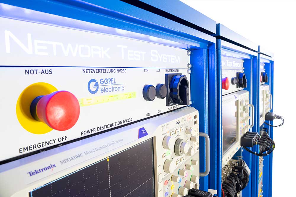
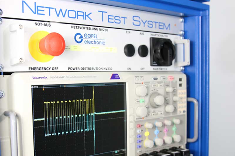
A network testing system allows statements on the physical properties of bus interfaces, the checking of communication properties as well as the simulation of transfer fields on the individual control device, even in a group.

With the combination of measurement technology and diagnosis functions within the network system, this allows special network tests to be realised, the carrying out of which was previously often costly and not automated.

The network test determines whether a control unit can send and receive data to the right specification under all possible operating conditions in the motor vehicle. Whether a control unit affects communication within the vehicle environment or in the case of disrupted communication carries out unchecked reactions can be checked with the network testing system.

» Test Cases - Specifications

Testing and validation of automotive ECUs in development

MagicCAR compact

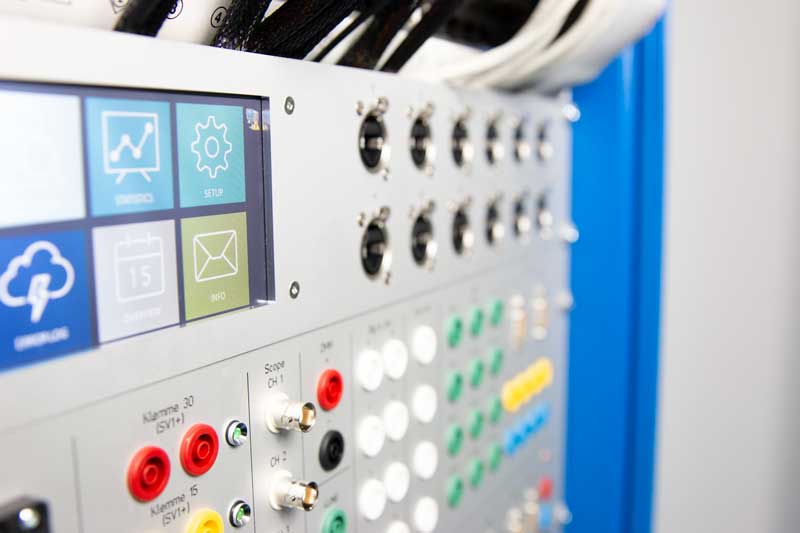
MagicCAR compact is a compact desktop testing environment for in-vehicle network testing and functional testing in one device. The system has a programmable power supply with switchable terminal signals and integrated current measurement. MagicCAR Compact Net is your solution for automotive networking tests and many other applications.

» more information on MagicCAR Compact

Determination of the sampling time for CAN/CAN-FD

Sample Point System

The Sample Point System is a system to determine the sampling time for CAN/CAN-FD. The box is an optional add-on for the standard network test system by GOEPEL electronic. The Sample Point System allows determination of the sampling time with modified CAN/CAN-FD frames even in case of collisions (simultaneous bus access) and thus under real conditions. The collisions are reliably detected and specially handled. The measurement is repeated with the current parameters.

Highlights

  • Patented collision tolerant method
  • Measurement of the sample point for CAN/CAN-FD (arbitration and data phase)
  • +/- 1 % accuracy of measurement

Connection to the network test system is realized via the Ethernet host interface.
The test sequencer software from GOEPEL electronic ensures easy integration of the measurement.

Service

GOEPEL electronic supports you with the development-related qualification of ECUs and their tests. The concrete error analyzes can be integrated directly into your developments and thus secure your own projects. Through the creation of automated and reproducible test sequences, progress is documented.

Focus of the Network Test System:

  • CAN is considered to be the oldest bus system in the vehicle. The sensor/actuator protocol has been established since the early 1990s. The CAN (Controller Area Network) communication system is widely regarded as proven, robust and reliable - and today it is the dominant protocol in automobiles.

    The constantly growing demands on data rate and transmission speed led to the evolution as CAN-FD (Flexible Data Rate). The bit rate limitation of 1 Mbit/s of the CAN could thus be increased to up to 8 Mbit/s of the CAN-FD standard. In addition, the number of data bytes per CAN frame was increased from 8 to 64 - with the same cabling.

    CAN-FD is standardized as ISO11898-1:2015 and downwardly compatible with classic CAN communication.

    » Click here to learn more

  • The FlexRay communication bus is primarily used for safety-relevant and time-critical applications. FlexRay offers a comparatively high data transmission rate, real-time communication and high reliability. FlexRay can be operated redundantly using two parallel buses, i.e. if one line fails, the other can take over.

    The time at which a node is allowed to transmit is determined on the basis of a global cyclic transmission schedule. If the transmission is interfered with by electrical disturbances, faulty data contents are detected by the FlexRay controller, so that they can usually be handled safely by the ECU software.

    The high safety standard is also required for X-by-wire applications, i.e. drive-by-wire, steer-by-wire or brake-by-wire, which will become even more relevant in electric vehicles in the future.

    » Click here to learn more

  • Automotive Ethernet is increasingly being used for the future of networked vehicle architectures.

    Driving assistance systems / ADAS, autonomous driving and networking between cars and the environment (Car2X / V2X, Car2Car) are applications that are still in their early stages, but which will sooner or later be used more and more. Automotive Ethernet is the generic term for BroadR-Reach (100Base-T1) and its further development RTPGE (Reduced Twisted Pair Gigabit Ethernet, 1000Base-T1).

    A large bandwidth is intended to create standardization that connects increasingly complex electronic components in the vehicle and provides uniform interfaces for hardware and software.

    » Click here to learn more

  • Low Voltage Differential Signaling is an interface standard for high-speed data transmission. The standard describes only the physical layer, not the protocols based on it. The achievable data rate is several GBit/s.

    LVDS is mainly used at the interface between human and machine: the displays for driver assistance systems and infotainment.

    The distances between the image generator (e.g. the camera at the rear of the car) and the display (in the console) are often long. In addition to a high bandwidth for high-resolution 4 k / 8 k video data, real-time transmission is of utmost importance for safety reasons. In the quality assurance of such driver assistance and infotainment systems, the main task is therefore to analyze the data on the "data highway" and to detect errors during transmission between the end points.

    LVDS Frame Grabber
    The LVDS frame grabber is a device used to record and store image data (frames) that are sent to a display via an LVDS connection. Transmitters of this image data are, for example, cameras or sensors. In a host system, the image data is displayed on a monitor or compared with reference images or further processed.

    LVDS Frame Generator
    In the opposite direction to the grabber, a frame generator can control displays and generate images without the need for a control unit. In this way, e.g. displays and digital combination instruments can be tested.

    » Click here to learn more

Test Scenarios - Network Test

  • bus physics
  • parameters
  • supply
  • data definition
  • fault management
  • network management
  • diagnosis
  • function

Test Cases - Specifications

CAN / CAN-FD

  • Cross section requirement specification HS_CAN_LAH_V57F
  • VW 80110, VW 80111, VW 80118, VW 80000
  • VW End-to-End Communication Security
  • DT Network Management Specification
  • JLR Design Verification Method for CAN Network Management
  • FIAT Off-vehicle physical level test 7-Z0145
  • BMW, FORD Conformance
  • Other

LIN

  • Conformance Test Specification Package for LIN 2.1
  • VW LIN group specification (KLH) 2.1.2
  • VW LIN test specification 1.6
  • DT LIN component tests
  • Other

Automotive Ethernet (BroadR-Reach)

  • Residual bus simulation (with/without switch)
  • Connection tapping
  • Gateway functionality test
  • Functions for DoIP and SOME/IP

FlexRay

  • VW group specification (KLH) 1.6
  • VW network test specification FlexRay 1.7
  • End-to-End
  • Other

Diagnostics

  • VW 80124
  • VW KWP2000 on TP20 1.2
  • Test specification ISO-TP 1.2 according to ISO 15765-2 / -4
  • Other

More about Network Tester

Events

Nous nous excusons. Aucun événement disponible pour le moment.
×
Vous avez besoin d'aide ?

Contactez nous !

Michael Schmidt
M. Michael Schmidt
×
Vous avez besoin d'aide ?

Contactez nous !

Automotive Test Solutions